- 您现在的位置:买卖IC网 > Sheet目录1991 > CS5364-CQZR (Cirrus Logic Inc)IC ADC 4CH 114DB 216KHZ 48-LQFP
DS625F4
23
CS5364
4.5.2
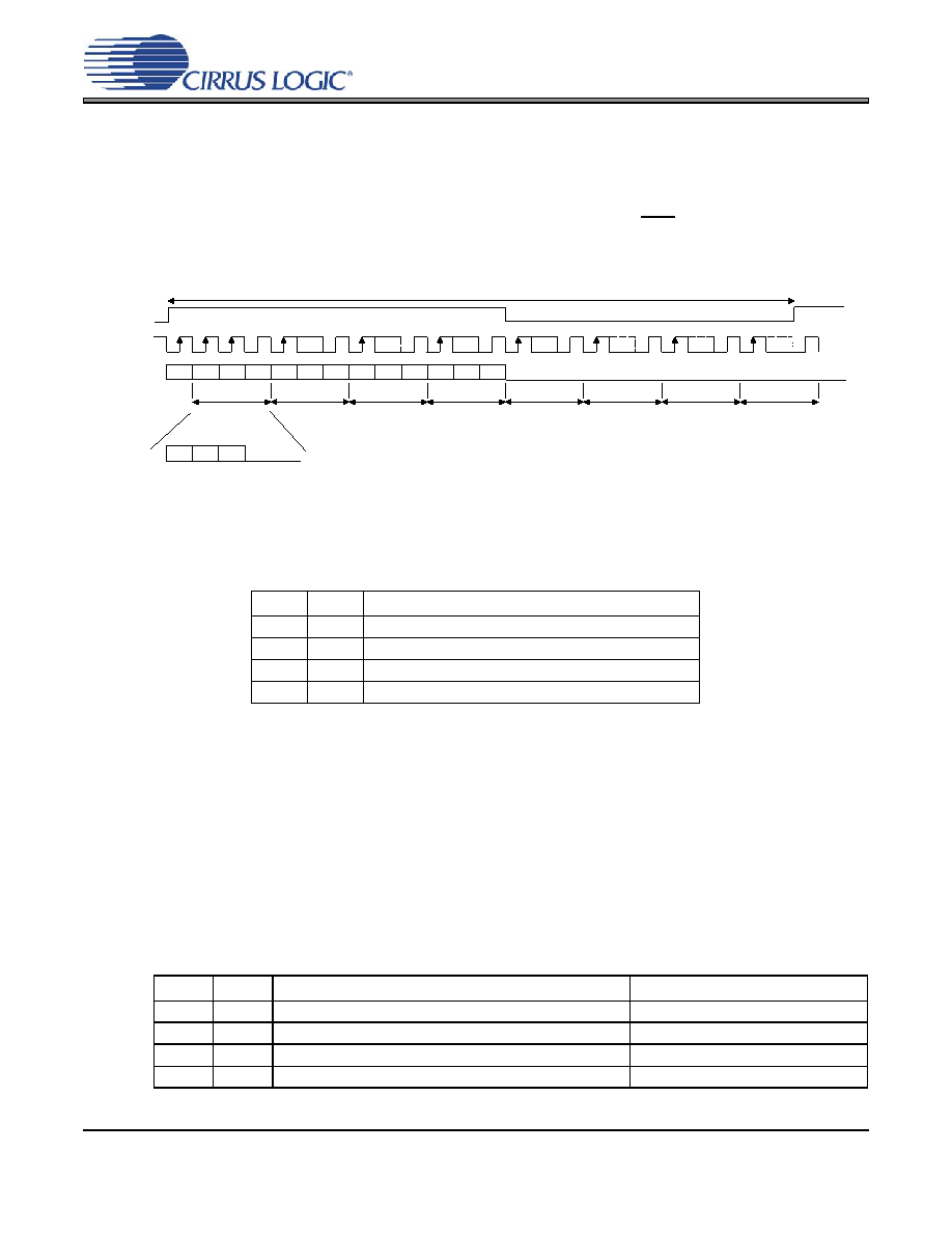
TDM Format
In TDM Mode, all four channels of audio data are serially clocked out during a single Frame Sync (FS) cy-
cle, as shown in Figure 12. The rising edge of FS signifies the start of a new TDM frame cycle. Each chan-
nel slot occupies 32 SCLK cycles, with the data left justified and with MSB first. TDM output data should be
latched on the rising edge of SCLK within time specified under ‘Serial Audio Interface - TDM Timing” section
on page 16. The TDM data output port resides on the SDOUT1 pin. The TDM output pin is complimentary
TDM data. All SDOUT pins will remain active during TDM Mode. Refer to Section 4.11 “Optimizing Perfor-
mance in TDM Mode” on page 29 for critical system design information.
Figure 12. TDM Format
4.5.3
Configuring Serial Audio Interface Format
The serial audio interface format of the data is controlled by the configuration of the DIF1 and DIF0 pins in
Stand-Alone Mode or by the DIF[1] and DIF[0] bits in the Global Mode Control Register in Control Port
Mode, as shown in Table 2.
Table 2. DIF1 and DIF0 Pin Settings
4.6
Speed Modes
4.6.1
Sample Rate Ranges
CS5364 supports sampling rates from 2 kHz to 21 kHz, divided into three ranges: 2 kHz - 54 kHz, 54 kHz -
108 kHz, and 108 kHz - 216 kHz. These sampling speed modes are called Single-Speed Mode (SSM),
Double-Speed Mode (DSM), and Quad-Speed Mode (QSM), respectively.
4.6.2
Using M1 and M0 to Set Sampling Parameters
The Master/Slave operation and the sample rate range are controlled through the settings of the M1 and
M0 pins in Stand-Alone Mode, or by the M[1] and M[0] bits in the Global Mode Control Register in Control
Port Mode, as shown in Table 3.
Table 3. M1 and M0 Settings
DIF1
DIF0
Mode
0
Left-Justified
01
IS
10
TDM
11
Reserved
M1
M0
Mode
Frequency Range
0
Single-Speed Master Mode (SSM)
2 kHz - 54 kHz
0
1
Double-Speed Master Mode (DSM)
54 kHz - 108 kHz
1
0
Quadruple-Speed Master Mode (QSM)
108 kHz - 216 kHz
1
Auto-Detected Speed Slave Mode
2 kHz - 216 kHz
SCLK
LSB
MSB
LSB
MSB
LSB
MSB
TDM OUT
Channel 1
Channel 4
Channel 2
Channel 3
32 clks
FS
LSB
MSB
LSB
MSB
Data
Zeroes
发布紧急采购,3分钟左右您将得到回复。
相关PDF资料
CS5366-DQZR
IC ADC 6CH 114DB 216KHZ 48-LQFP
CS5368-DQZ
IC ADC 8CH 114DB 216KHZ 48-LQFP
CS5381-KSZ
IC ADC AUD 120DB 192KHZ 24-SOIC
CS53L21-CNZR
IC ADC STEREO 24BIT 98DB 32-QFN
CS5509-ASZR
IC ADC 16BIT SGL SUPP 16-SOIC
CS5512-BSZ
IC ADC 20BIT EXTERNAL OSC 8-SOIC
CS5526-BSZR
IC ADC 20BIT W/4BIT LATCH 20SSOP
CS5528-ASZR
IC ADC 24BIT 8CH 24-SSOP
相关代理商/技术参数
CS5364-DQZ
功能描述:音频模/数转换器 IC 114dB 192kHz 4-Ch ADC w/TDM Interface RoHS:否 制造商:Wolfson Microelectronics 转换速率: 分辨率: ADC 输入端数量: 工作电源电压: 最大工作温度: 最小工作温度: 安装风格: 封装 / 箱体: 封装:
CS5364-DQZR
功能描述:音频模/数转换器 IC IC 114dB 192kHz 4ch ADC w/TDM Intrfc RoHS:否 制造商:Wolfson Microelectronics 转换速率: 分辨率: ADC 输入端数量: 工作电源电压: 最大工作温度: 最小工作温度: 安装风格: 封装 / 箱体: 封装:
CS5366
制造商:CIRRUS 制造商全称:Cirrus Logic 功能描述:114 dB, 192 kHz, 6-Channel A/D Converter
CS5366_08
制造商:CIRRUS 制造商全称:Cirrus Logic 功能描述:114 dB, 192 kHz, 6-Channel A/D Converter
CS5366_09
制造商:CIRRUS 制造商全称:Cirrus Logic 功能描述:114 dB, 192 kHz, 6-Channel A/D Converter
CS5366-CQZ
功能描述:音频模/数转换器 IC 114dB 192kHz 6-Ch ADC w/TDM Interface RoHS:否 制造商:Wolfson Microelectronics 转换速率: 分辨率: ADC 输入端数量: 工作电源电压: 最大工作温度: 最小工作温度: 安装风格: 封装 / 箱体: 封装:
CS5366-CQZR
功能描述:音频模/数转换器 IC IC 114dB 192kHz 6ch ADC w/TDM Intrfc RoHS:否 制造商:Wolfson Microelectronics 转换速率: 分辨率: ADC 输入端数量: 工作电源电压: 最大工作温度: 最小工作温度: 安装风格: 封装 / 箱体: 封装:
CS5366-DQZ
功能描述:音频模/数转换器 IC 114dB 192kHz 6-Ch ADC w/TDM Interface RoHS:否 制造商:Wolfson Microelectronics 转换速率: 分辨率: ADC 输入端数量: 工作电源电压: 最大工作温度: 最小工作温度: 安装风格: 封装 / 箱体: 封装: